
The drawing
Beside the realistic look TRAX has a second one: CAD, the technical drawing. It is not the same layout with another skin over it — it is the look in which you measure, put dimensions on and check that your design works.
- The construction drawing (CAD) — what you see and what changes.
- Dimensions and notes — putting lengths, angles, heights and texts into your drawing.
You switch with  CAD in the Look group on the View tab, and back with
  Realistic.
When do you use CAD?
Realistic shows what your layout looks like; CAD shows whether it is right. Reach for CAD when you:
- want to read your track plan without trees, grass and shadow getting in the way;
- want to measure: the dimensions of your tables are there by themselves, and you add lengths, angles and heights yourself;
- want to see the article numbers, to order your track or check it;
- want a picture to take along to the timber merchant or the model railway shop;
- are checking a layout from TRAX2: without a drawn landscape it opens in CAD.
8.1 The construction drawing (CAD)
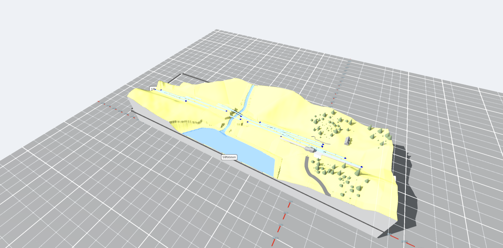
What you see
CAD shows only what you need to understand the layout:
- No textures. Every part takes a flat colour for what it is: platform, road with its middle line, wall, fence, hedge, water, quay.
- No grass and no small stuff. Those are gone.
- Trees become a shape. A cone for a conifer, a ball for a broadleaf, a crown on a bare trunk for a palm, a dome for a bush — each with the real height and width of the model standing there. That keeps the drawing readable and you still see where your wood is.
- Buildings turn mid grey.
- Nothing moves. No wind, no waves.
Shadow, though
The shadows stay on. A flat drawing without shadow cannot be read in three dimensions: you would not know whether a surface runs up or down. The light is different — much more ambient light and a weaker sun — so that the flat colours keep their colour.
Ink lines
The Settings panel has Ink lines. It draws a line around the outline of everything, the way a draughtsman does. In CAD it is on by default; it works in the realistic look too if you like it there.
The tables' dimensions
In CAD every side of every table longer than 150 millimetres is dimensioned, in grey, just outside the table. They appear by themselves and disappear again when you go back to realistic. They do not belong to your layout and are not saved with it.
Double-click such a dimension and you can type it in. The table is then stretched along that side until the measurement is right — a rectangle stays a rectangle. That is how you make a table of exactly 2400 by 600 without dragging.
Marking emplacements
A station, a yard, a staging yard or a siding: that is something you know, and TRAX cannot always read it from how the track lies. A terminus of four roads behind buffer stops looks exactly like a goods yard or a staging yard. So you can mark it yourself, on the CAD tab in the Emplacements group:
 Select the track that belongs to it and click Mark the selected track as a new emplacement. A coloured band appears under that track, with a name plate on it.
 With the next two buttons you add selected track to the chosen emplacement, or take it out. A piece of track always belongs to one emplacement at most.
- Show switches the bands and plates on or off.
Click the name plate and the emplacement is selected. You then get its own tab:
- On the left, how many pieces of track belong to it.
- Type: station, halt, yard, staging yard, depot, siding or industrial siding.
- Name: what you call it. Left empty, it is named after its type.
 Select its track selects all the track of the emplacement, so you can move, copy or cut it as a whole.
 Remove this emplacement only takes the marking away. The track stays where it is.
What is saved is which pieces of track belong to it, not a drawn shape. Move the station or lay a track beside it, and the band follows by itself.
Every look remembers its own settings
Choose CAD and TRAX turns the outlines, the labels and the grid on and the textures off. After that those switches are yours again, and TRAX remembers per look what you chose. Your layout is saved with the look that was on.
8.2 Dimensions and notes
The moment you choose the CAD look a tab joins them: CAD. That is where the measuring tools are.
The four kinds
 Measure a length — click two points. You get the distance between them.
- Measure an angle — click a point, then the corner, then a point. You get the angle.
 Note a height — click a point. You get a T mark, as on a track plan, with that point's height above the rail level.
 Place a text — click a point and type your text.
You click on anything that is there: on a table, on the ground, and on the track itself. So a height note on a rail says exactly what level that track lies at.
A click during which the mouse moved more than a few pixels counts as a camera move, not as a measurement. Esc cancels.
Snapping to fixed points
When the mouse comes close to a fixed point, the measuring point snaps onto it exactly. An orange ring shows where. Fixed points are:
- the track's connections, the dots where two pieces meet;
- a table's corners, and a table's edge;
- the middle, the corners and the sides of a building or object;
- a platform's corners;
- the point of a height note or a label.
So you measure, for example, exactly from the end of a turnout to the edge of the table, without having to aim.
Straight along an axis
When your measuring line runs nearly parallel to one of the axes, TRAX3D lays it exactly along it. The line then takes that axis's colour: red along the X axis, blue along the Z axis. A fixed point comes first: it is never moved, it only takes the axis's colour when it already lies exactly on the axis.
When the point snaps to a table's edge or a building's side, both can happen at once: the point slides along that edge to where the axis crosses it. It is then on the edge and the line runs straight.
The measurement stays fastened
A measuring point remembers what it is fastened to: the track, the table, the object, or the height note or label you clicked on. If you then move the track, the table or the building, the measurement moves with it and its number follows by itself. So a dimension in your drawing always stays right.
Typing a dimension
Double-click the label of a length and type the length you want. TRAX3D then slides one of the two ends along the dimension line until the dimension is right.
Which end moves depends on how firmly it is held. What is held least moves:
- first a loose point, fastened to nothing;
- then a building or object;
- then the track, with everything fastened to it;
- then a height note or a label;
- and a table last.
When both ends are held equally, the second point you clicked moves. An end that would carry the other along stays put: measure from a rail to the corner of the table that rail lies on, and the rail moves, not the table. When it cannot be done, for example because both ends are fastened to the same thing or because the track is locked, TRAX3D says why.
One undo takes the move back.
Changing a note
Click a note, on the label itself. The CAD tab turns to it and you can change two things:
- the text. On a label that is the text itself; on a measurement it is a name put in front of the value, for example Radius 500mm.
- the colour, from a row of eight.
or Delete removes it.
How they are drawn
The lines are real fat ink lines of three pixels — an ordinary line in 3D is always one pixel thick, however you set it. The text stands on a plate that always keeps the same size on your screen, however far you zoom in or out. At the scale of a table, a text of a real size would simply vanish.
A line behind a hill is covered by that hill. When a dimension runs straight through the ground, for example between two height notes with a hill between them, you see that part of the line faintly. The label is always in front, so a dimension never disappears altogether.
They belong to your layout
Notes are saved with your layout and are there again next time. They are only visible in the CAD look: they belong to the drawing, not to the landscape.
A measurement may run across two tables — the dimensions are in world coordinates, not per table.
8.3 Checks
TRAX can check your layout while you build. It does so in the CAD look, and only when you ask: the checks are off until you switch them on. While they are on, TRAX checks the layout again after every change — a piece of track laid, moved or raised, a table reshaped, an undo — and puts a sign where something is not right.
The button on the CAD tab
 Check the layout is on the CAD tab of the ribbon. Press it and TRAX checks the layout and shows what it finds, and keeps doing so while you go on drawing. Press it again and the checks go off: every sign disappears.
Outside CAD the checks are always off. Switch back to Realistic and they go off by themselves, and nothing is calculated either.
What is checked
Every kind of problem has a sign of its own: a white round sign with a red ring and a picture in it. An orange ring is a warning.
 Grade — a piece of track steeper than the maximum grade in the settings (3 % on straight track, 2 % in a curve) turns red. Between 95 and 105 per cent of that maximum it turns orange: still allowed, but nothing to spare.
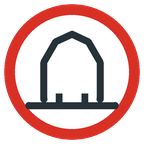 Loading gauge — a strip round the track has to stay clear: two metres either side on the real railway, scaled down to your scale, and a little more in a curve, where a coach swings out. Another track, a building, a wall, a fence, a hedge or a catenary mast inside it gets this sign. A platform may come closer, to one and a half metres from the centre line.
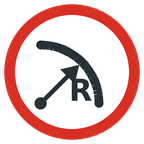 Minimum radius — mostly for flex track: where the curve gets tighter than the minimum, the sign stands at the tightest spot. The minimum is automatically the smallest curve of the track system itself, so an ordinary sectional piece is never too tight.
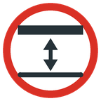 Clearance height — where track runs over track, TRAX measures the room between the top of the lower rails and the underside of the upper ballast bed. On the real railway that is at least 4.8 metres; in H0 it is 55 millimetres.
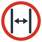 Track spacing — two tracks running side by side need at least the spacing of the norm (NEM 112: 46 millimetres in H0), and more in a curve. The spot where they come closest gets a red dimension line with the distance measured.
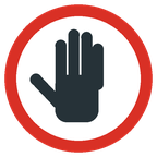 Reach — a part of a table farther than an arm's length (600 millimetres) from the nearest edge cannot be reached. That part is hatched red. TRAX assumes you can stand at every edge.
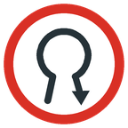 Reversing loops — a reversing loop, a wye or a balloon loop brings a rail round onto its own other rail. That is a short circuit. The pieces of the loop turn red; they need isolated sections at least as long as your longest train, and a reversing module or a polarity switch.
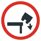 Table edge — track closer to the edge of its table than three metres on the real railway (34 millimetres in H0, measured from the centre line) gets the sign at the tightest spot. That keeps a whole train above the table, with room for your hand and for a wagon that tips over. A piece marked as a bridge does not count, and the side where another table or module joins on is not an edge.
Open ends that only just miss each other are not reported: the dots already show those.
The explanation at a sign
Click a sign and a small explanation appears beside it. It says:
- which check it is, and what is wrong at this spot, with the measured value against the limit — for example Grade 3.4 % — maximum 3 %;
- why that matters;
- what you can do about it.
At the bottom are two buttons. Ignore ignores this problem, just like the eye in the Checks panel. Read more in the manual opens this page. The explanation closes with a click anywhere else or with Esc. A click on a sign never selects the table or the track behind it.
The Checks panel
 You open the Checks panel on the CAD tab, beside the button that turns the checks on, or it opens by itself as soon as you turn them on. It lists every problem, grouped by kind, with the count beside it and each with the sign of its kind.
- Click a row and the camera goes to that spot. The track that belongs to it is selected straight away.
 Ignore a problem you are leaving that way on purpose. It leaves the list and the drawing and goes under Ignored, where you can bring it back. What you ignore is saved with your layout.
- At the top is the switch for all the checks at once. It is the same switch as the button on the CAD tab: switch one on and the other is on too. Outside CAD it is greyed out.
- Below it, every check has a switch of its own.
- Under Limits you can give the minimum radius, the distance to the table edge and the arm's length yourself. A 0 means: automatic.
In the drawing
The signs keep the same size on your screen however far you zoom in or out. TRAX draws a little more: a pale red strip the width of the loading gauge along all the track, and the hatched parts of a table that are out of reach.